Antenna measurement center

TDF's CMA, a center of excellence for antennas, environment and radio cohabitation

Contents

Our experts carry out all the antenna measurements required for your projects.

Far from any source of electromagnetic disturbance, TDF's CMA (Centre de Mesures d'Antennes), located in Liffré in the Ille-et-Vilaine region of France, has several separate bases for the complete characterization of all types of antennas and radiating structures over a wide spectrum, from a few hertz to 50 GHz.

The CMA brings its expertise and knowledge of innovative technologies to its customers to solve the most complex problems:

  • Amplitude/phase radiation diagrams,
  • Gain, adaptation,
  • Decoupling, polarization purity and system immunity.

Customized services

Comprehensive studies to meet our customers' needs

Engineering and design

CMA designs and develops customized
antenna solutions for both civilian and military
applications, across the entire
radio spectrum.

  • Study
  • Prototypes
  • Antenna design

Simulations and Expertises

CMA realizes:

  • Optimized positioning of antennas on support structure
  • Assessing inter-system decoupling
  • Prediction of service areas in the
    VLF/LF/MF frequency bands (Ionospheric,
    surface waves)

Powerful simulators

Our experts use:

  • 3D electromagnetic simulation tools(CST Studio suite - NEC4)
  • Mechanical modeling tools (Solidworks - Autocad)
  • Proprietary solutions

A top-class team

Made up of technical experts, engineers and PhD students, the CMA team covers a field
of expertise that is unique in France, to meet the most demanding requirements.

The originator of numerous patents, the company designs and commissions innovative antennas for its own needs as well as for customers in the
audiovisual, telecoms, IoT, defense and security sectors.

antenna measurement and design center
Technicians install antenna

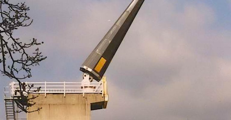
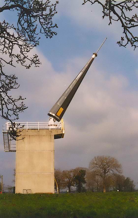
Multifunction base

30 MHz - 3,8 GHz

The buried azimuth positioner and rotating and rotating dielectric arm are used to produce horizontal and vertical diagrams within a hemispherical volume above-ground hemispherical volume.
antenna measurement center multifunction base 1
antenna measurement center multifunction base 2

Technical data

Maximum capacity: nearly 2 tonnes

- Measuring radius: 5 meters
- Interchangeable brackets allow
vehicles (cars, motorcycles...)
to be installed, as well as equipped people and structures with integrated antennas.

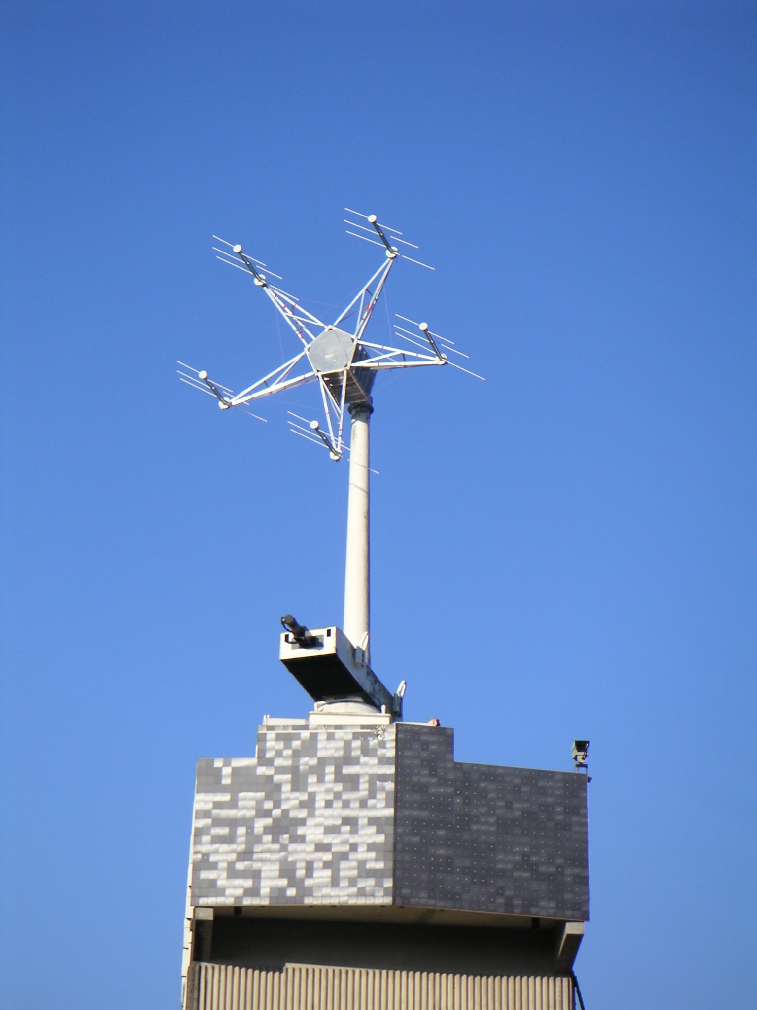
Base de mesure champ proche

30 - 400 MHz

La base multifonctions peut également être configurée pour effectuer des mesures en champ proche. Une acquisition complète (sous forme de « boite de Huygens » parallélépipédique avec ses 4 faces latérales + face supérieure) peut être exportée vers des logiciels de simulation électromagnétique, pour faire rejouer ce modèle numérique dans n’importe quel environnement virtuel, sans nécessiter la connaissance préalable des constituants internes de l’antenne.

base de champ proche simulation
base de champ proche image

Technical data

• Bande 30 400 MHz
• Acquisition de multiples fréquences simultanément
• Environnement proche pur (bras diélectrique, liaison fibres optiques, sondes électro-optiques)
• Etude complète d’un projet d’implémentation antennaire (acquisition champ proche, génération modèle numérique, simulation électromagnétique)

Anechoic chamber

1 - 50 GHz

center mesures antennes chambre anechoique
cma anechoic chamber 2

Of respectable dimensions, the anechoic chamber at
CMA enables antennas from 1 GHz to
50 GHz to be characterized in an environment free from reflections
and immune to external disturbances.

Thanks to its removable TEM cell, gain measurement, even
very low, is possible from a few hertz up to 150 MHz, while full faradization allows advanced
immunity and sensitivity tests.

Technical data

Dimensions: 20 m x 9 m x 9 m

- 4-axis positioner (azimuth, elevation, off set, polarization)
- Measuring distance: 15 m
- Reflection-free environment¹
- 4-axis positioner (azimuth, elevation, off set, polarization)
- Faradization greater than 100 dB at wave 2


1 reflectivity better than 40 dB
² 84 dB @15 kHz magnetic field protection, 120 dB @100 MHz electric field protection, 110 dB @36 GHz and 90 dB @96 GHz plane wave protection

Groundwave base station - VHF - UHF

60 MHz - 1 GHz

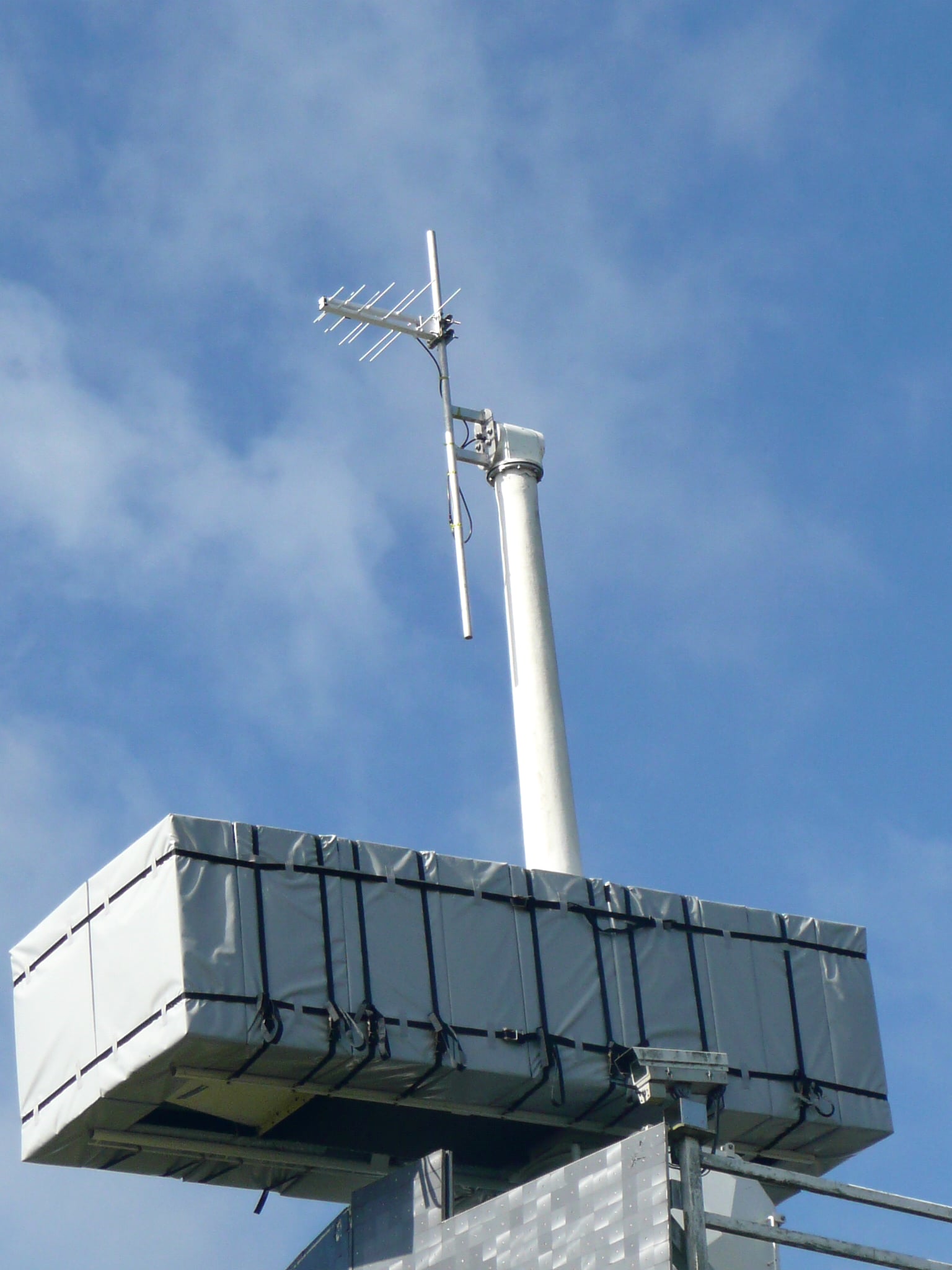
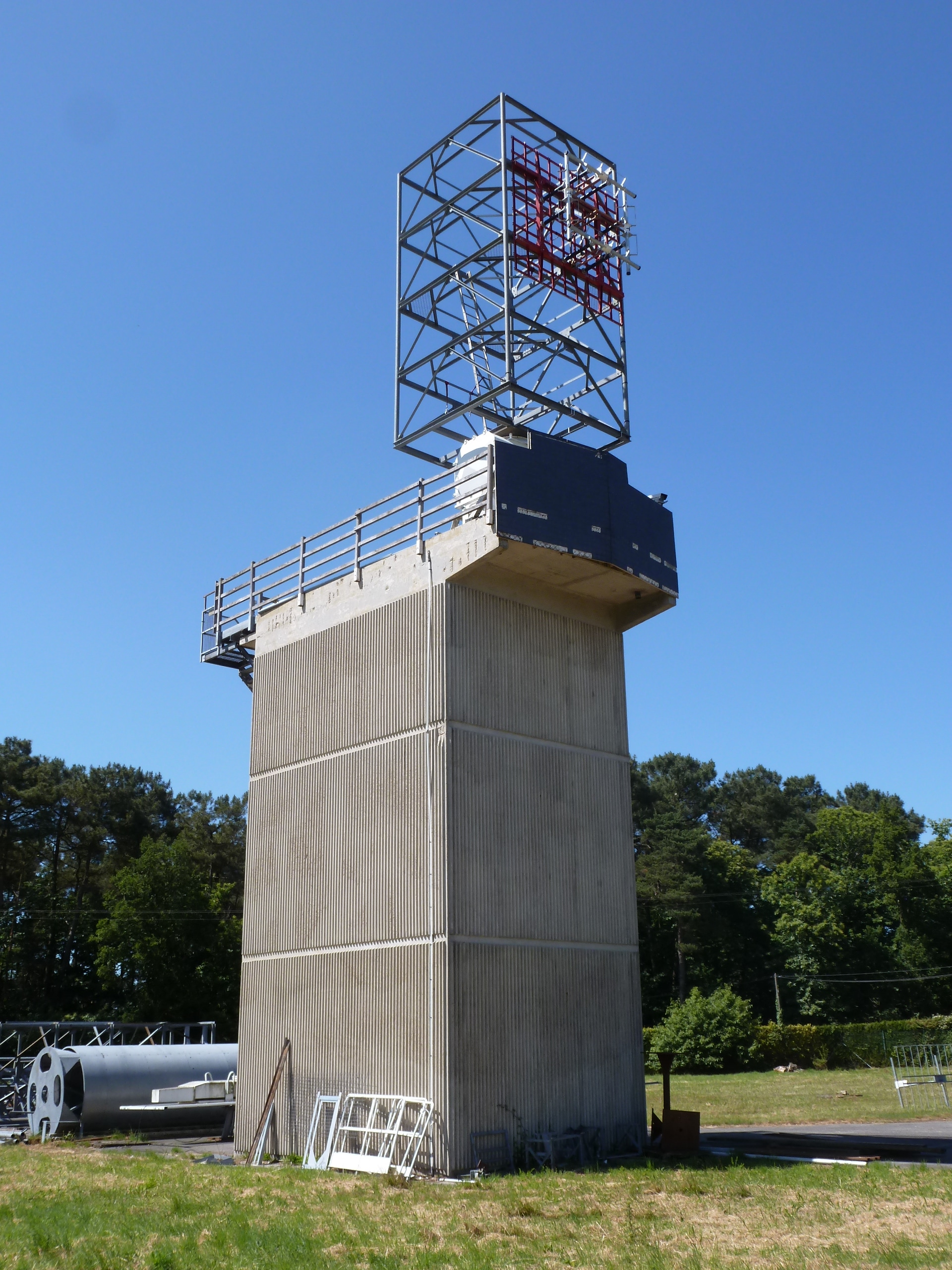
The groundwave base enables in situ qualification of antennas in situ, in the presence of their support, whether CMA or external structures.

Its operating principle ensures phase matching
between the direct wave and the wave reflected on the ground.

It therefore guarantees free-space measurement conditions.

The measurement of obliquely or circularly polarized antennas is made possible by recording the horizontal and vertical components
and vertical components, followed by post-measurement
conversion.

measurement center groundwave base antenna 4

Helicopter measurements

100 kHz - 1 GHz

Equipé d’un banc de mesure spécifique et homologué pour
des vols ruraux comme urbains, ce dispositif unique permet d’effectuer des relevés de diagrammes de rayonnement
azimutaux (vols circulaires) et en site (vols verticaux droits et en arc) sur l’ensemble du territoire, sur une très large portion du spectre radioélectrique.

cma helicopter measurements

Microwave base

1- 24 GHz

center for microwave base station antenna measurements 2

Two remote bases,
400 meters and 1135 meters apart respectively, enable
to measure large microwave antennas
in far-field conditions.
The hilly terrain and the high directivity
of the transmitting antennas (dishes)
limit reflections.

Technical data

Oversized 4-axis azimuth, elevation, low and high bearing positioner with 800 kg load capacity.
base microwave antenna measurement center 1